| bluepoof.com
email me
doing a valve adjustment.
Time needed: If it's your first time, give yourself most of the day. Once you do one set, it's a breeze, but getting everything off and figuring out the first set is a pain.
- 10mm socket wrench
- 12mm socket wrench
- 17mm socket wrench
- torque wrench
- flathead screwdriver
- 2 .012mm feeler gauges (you can get by with one, but having two makes it easier)
- 2 new gaskets for the cylinder head covers
background.
The VF750 is a V-four motorcycle, which means that there are two cylinder
blocks, arranged in a 90-degree V shape. Each block has two cylinders in it,
for a total of four cylinders. For the purposes of this text, the rear
block or rear cylinders will be the block that's accessible from the top of
the bike. These are cylinders 1 and 3, with cylinder 1 being the lefthand
cylinder as you sit on the bike. The front cylinders, or cylinders 2 and 4,
are those accessible from the front of the bike. Cylinder 2 is on your
lefthand side as you sit on the bike.
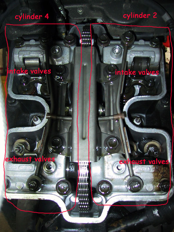
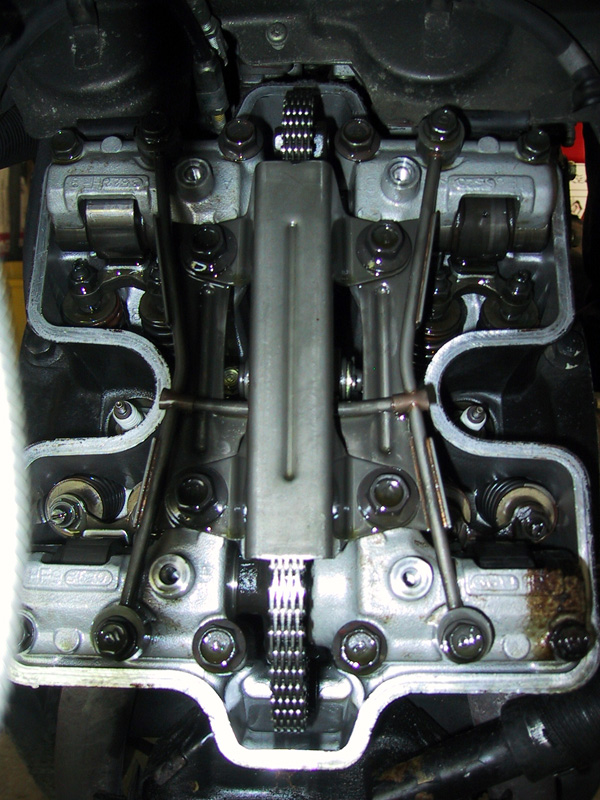
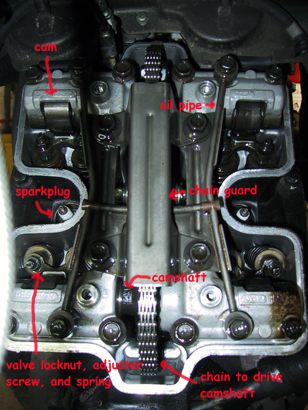
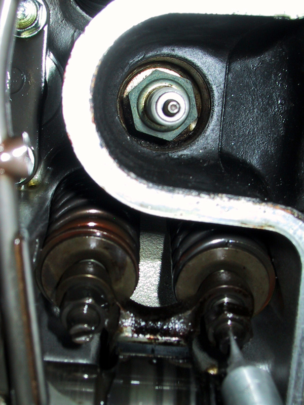
The VF750 has four valves per cylinder; two intake and two exhaust. The carburetors sit in the middle of the "V" formed by the cylinders; the exhaust pipes connect to the engine at the bottom of the engine. Therefore, the "top" valves are the intake valves; the "bottom" valves are the exhaust valves. Refer to the following picture of the front cylinder block for some much-needed clarification:
pre-procedure.
I don't have the VF Clymers in front of me, so unfortunately the pre-procedure
is going to be vague. I'll fill it in later when I borrow Peter's Clymers.
But before you do the valves on a VF750, you have to do the following:
- Remove the gas tank.
- Remove the upper radiator.
procedure.
The first thing to do is to remove the clylinder head cover. This is easy;
you just unscrew the four bolts holding it on (12mm, if I remember
correctly). Remove those bolts and their washers, and the covers will
come clean off. It's a good idea to replace the gaskets on these covers
before you put the covers back on; they run about $12 each. Remove the
covers and set them aside. This is easier said than done for the rear
cylinder block; for most of the procudure, we just had it tipped back out of
the way, since we couldn't get it off completely due to the frame. At some
point, Peter accidentally got it completely off, but I'm pretty sure you can
reach all of the valves with it just tipped back out of the way instead of
completely removed.
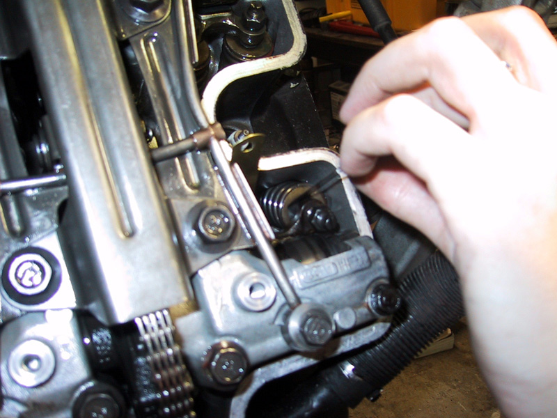
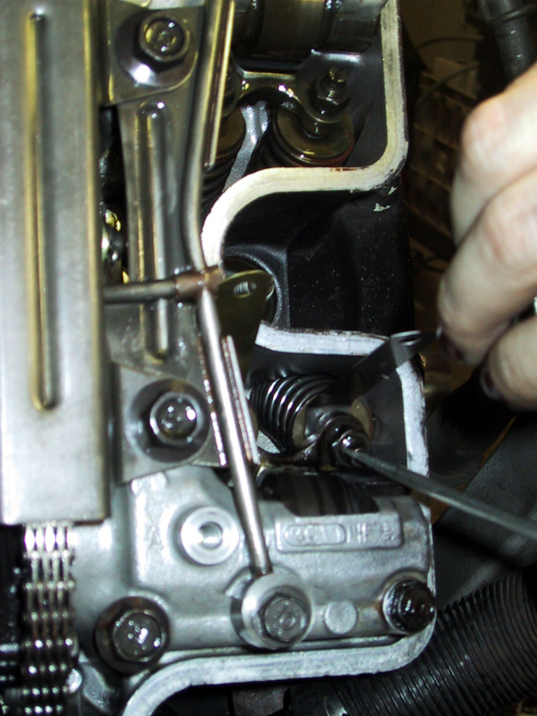
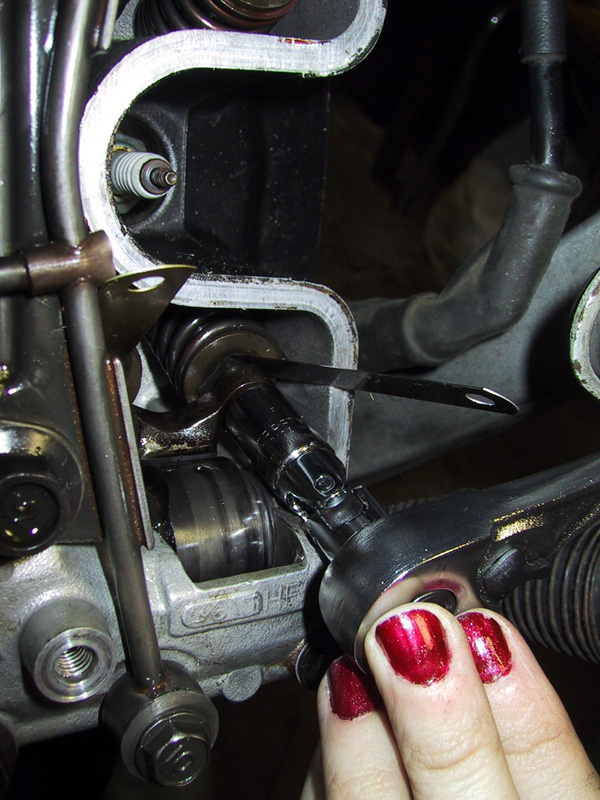
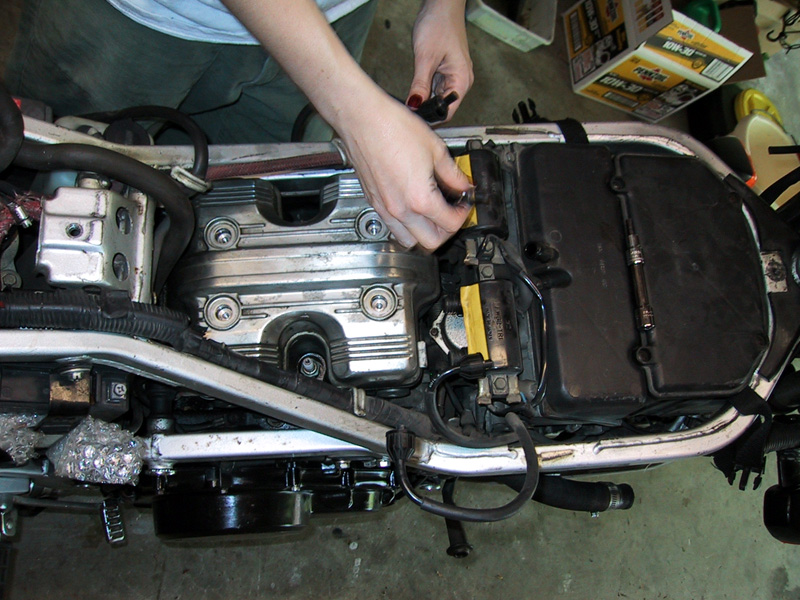
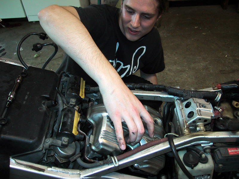
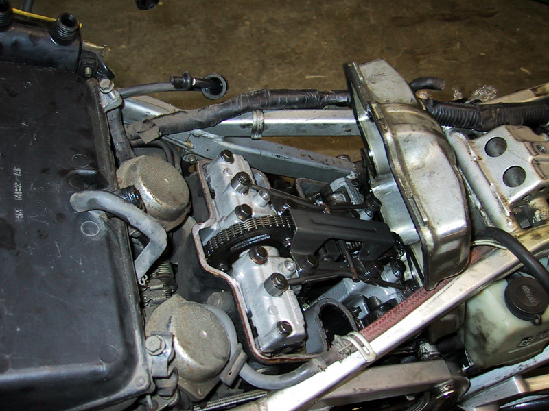
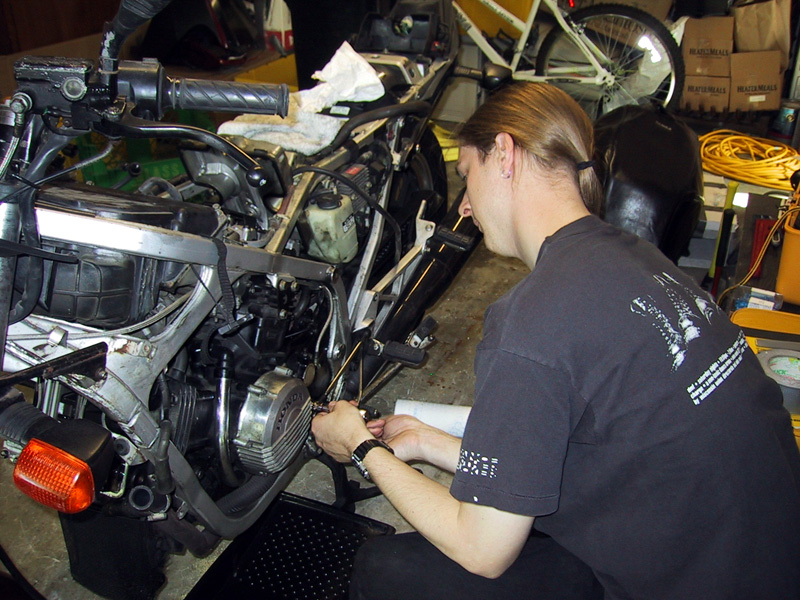
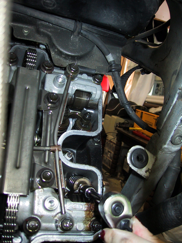
The first picture below is of me removing the sparkplug cables to try and get the cover off; it's a good view of the clyinder head cover. The front of the bike is to the right of the picture. The second picture is of Peter attempting to remove the cylinder cover. The third is the cylinder with the cover tipped out of the way.
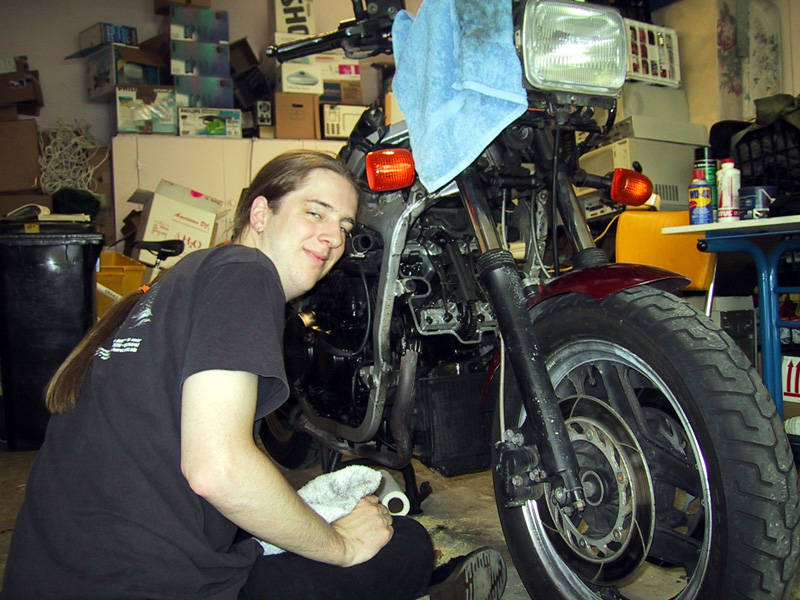
The rest of the procedural pictures will show the front clylinder block. In order to avoid confusion, here are some pictures to explain what's going on. The first is a really stellar picture of Peter with the front cylinder block. Second is a head-on shot of the block, and third is the same picture with labelling.
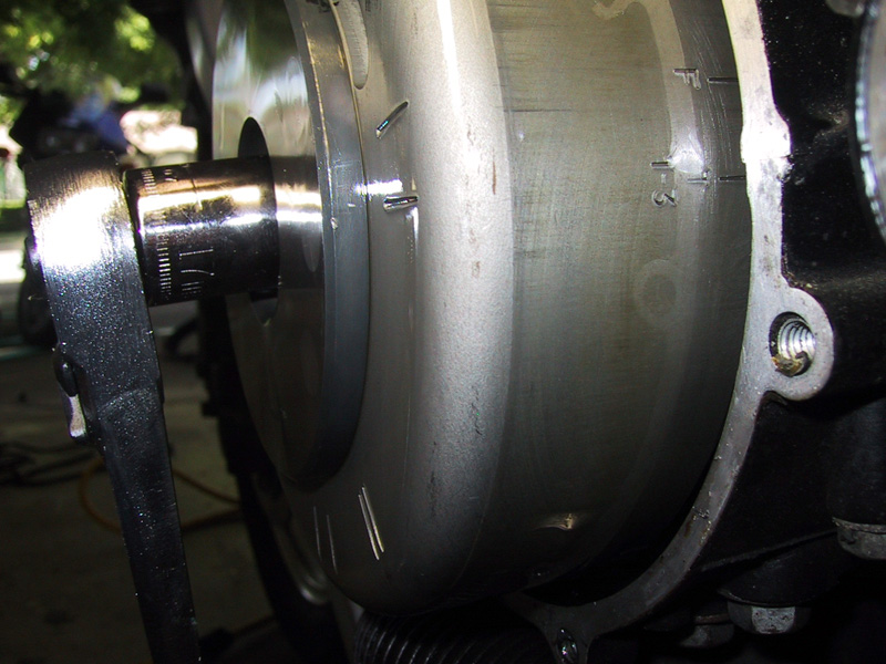
OK, now that everyone knows where we are, we can start actually working on the valves. The first thing we need to do is make sure that the cylinder that we're working on is at top dead center, or TDC. At TDC, the valves are all shut all of the way. Valves are pushed down inwards into the cylinder to open, so when they're shut, they're all the way up, which is the correct point at which to measure them for adjustment. In order to make sure that the cylinders are at TDC, we need to rotate the crankshaft; this physically pushes the cylinders through their four-stroke motions. While we were doing this, we actually took turns just rotating the crankshaft around while the other person watched the cams push open and shut the valves as the four strokes were completed. It's pretty cool to watch. Anyway. The crankshaft runs through the alternator; there are two separate markings on the alternator which we use to determine how far to turn the crankshaft. One is T 1-3 and the other is T 2-4. When you're doing the adjustment on the rear block, cylinders 1 and 3, you put a 17mm socket on the crankshaft and turn it until the "T 1-3" marking lines on the alternator line up with the molding line on the alternator cover (the horizontal line where the two pieces of metal that make up the cover meet). If you're doing cylinders 2 and 4 (the front block), you'll turn the crankshaft until "T 2-4" is lined up with the molding line.
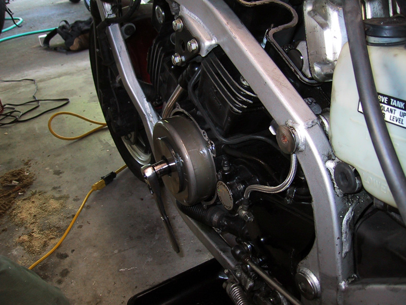
The first picture is of Peter removing the alternator cover. The second one shows the correct position for cylinders 1 and 3; you can see the marking saying "T 1-3" and the molding line on the cover is just above it The third picture is just a zoomed-out view, to give some perspective.
Now that everything's all lined up, we can finally start adjusting the valves. Yay! Since I had two .012mm feeler gauges, I tended to do both valves in a pair at once (i.e. both exhaust valves for cylinder 2). I recommend this, so that you don't get one valve out of whack while moving the rocker arm to adjust the second one.
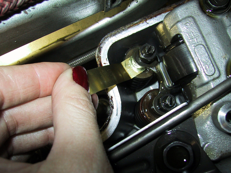
Take your handy-dandy .012mm feeler gauge and try to insert it between the valve spring and the adjuster screw [Note: these are the measurements for this particular bike, an '84 Honda VF750. If you have a different bike, your valve adjustment measurements will probably be different. Check your service manual for which feeler gauge you need to be using -- you don't want to mess this up.] You'll most likely need to bend the gauge so that it has a 90-degree angle at the bottom. This will make your life a bazillion times easier. I promise. The feeler gauge should fit snugly; there should be an eensy bit of drag when you move it around or pull it out. If there's any more room than this, or you can't get the feeler gauge in at all (which was our problem), you'll need to adjust the valves.
To adjust the valves, the first thing you do is loosen up the locknut that holds the adjustment screw in place. This is a 10mm bolt; you don't need to remove it, just break the torque seal and loosen it a little bit. Next, use a flathead sscrewdriver to loosen the adjustment screws. We loosened them just enough so that there was some play in the rocker arm (the horizontal metal piece which connects both valves).
After you've loosened everything, you'll stick the feeler gauge back under the adjustment screw. Since the screw is loose, you'll have to play a fun little balance game to keep the feeler gauges underneath the screw. Next, use your flathead screwdriver to tighten the adjuster screw. When you tighen the locknut, it'll move the screw slightly, so when you're tightening up the screw, don't tighten it all the way down so it's trapping the feeler gauge. Leave just barely enough room for the gauge to slide in and out without much drag. Once you've got that, go ahead and use your 10mm socket to tighten the locknut. When you're done with that, the feeler gauge should be able to be inserted and removed with a little big of drag. If you think you've got it, torque the locknut down to spec, and test the feeler gauges again.